
Clinical anatomy · 26 October 2026 · 12 min read
Lower molar
canal anatomy.
A root filling can look satisfactory while part of the canal system remains untreated. The position and shape of a distal opening can help you find a second canal, a broad extension or a connecting isthmus.

Canals seen on CBCT
First and second molars
| Lower molar | 3 canals | 4 canals |
|---|---|---|
| First823 molars | 79.9% | 15.4% |
| Second925 molars | 72.8% | 2.3% |
In this sample, four canals were more frequent in first molars.
01 / The source case
A distal lesion after root canal treatment.
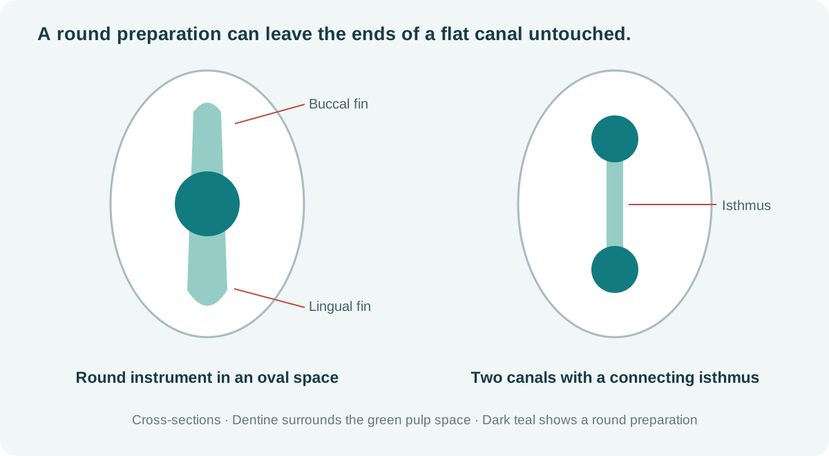
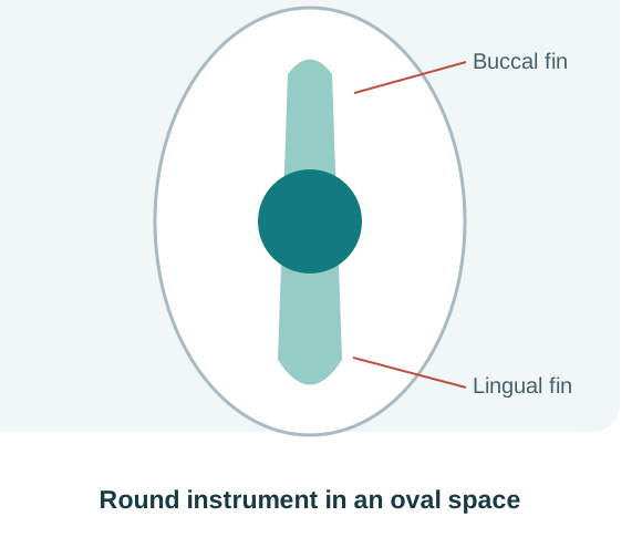
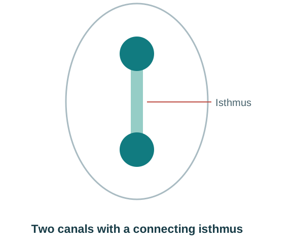
The linked reel from Endo simplified / إندو ببساطة presents a previously treated lower molar with a distal periapical radiolucency and a comparatively unremarkable mesial root. The presenter considers disinfection and fracture, then reports finding a second distal canal during retreatment.
The explanation moves from rectangular and triangular chamber-floor patterns to long-neck Munce burs, isthmuses and the recesses of broad distal canals. Examine the full distal anatomy before accepting the canal count.
This is the presenter’s case account. The reel does not provide a complete diagnostic record or documented long-term healing.
Watch the original reel ↗Source: Endo simplified. The original video remains on Facebook; access may require sign-in.
02 / Canal positions
Three or four canal openings.
Mesial: MB and ML
The mesiobuccal and mesiolingual entries generally occupy the buccal and lingual ends of the mesial floor–wall junction. A developmental groove may connect them. Below the floor, the canals can remain separate, communicate through isthmuses, or merge. Root count, opening count and apical exit count describe different things.
Distal: one broad entry, or DB and DL
A single distal opening may be oval or elongated buccolingually. If you suspect there could be two canals, look for distal buccal and distal lingual openings along the distal wall-distal floor wall junction. An opening at one end of that junction should prompt inspection of the other end; it does not prove that another canal exists. [1]
Triangular and quadrilateral patterns
The common three-entry arrangement forms a triangle; four entries often give a quadrilateral. The connecting grooves may resemble a Y or H. Those letters describe the chamber-floor pattern. The canals can divide or merge below it.
A single distal opening may lie lingual to the occlusal centre in second molars. [2]
Canals seen on CBCT
First and second molars
| Lower molar | 3 canals | 4 canals |
|---|---|---|
| First823 molars | 79.9% | 15.4% |
| Second925 molars | 72.8% | 2.3% |
In this sample, four canals were more frequent in first molars.
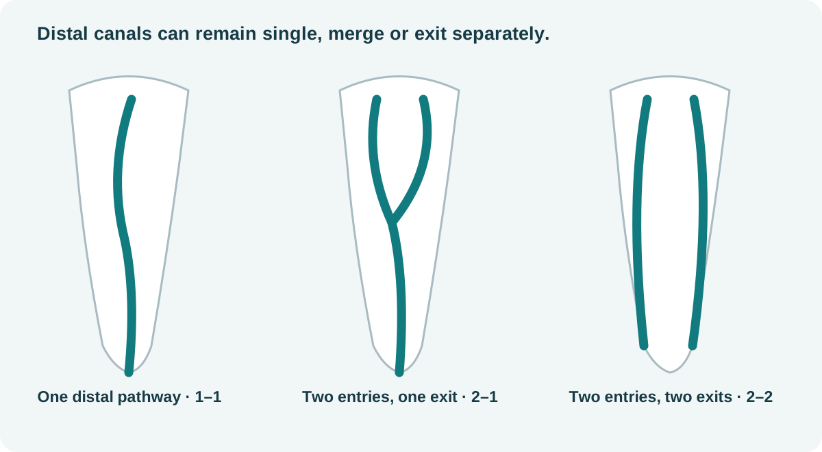
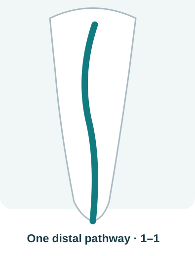 1 / 3 · One distal pathway
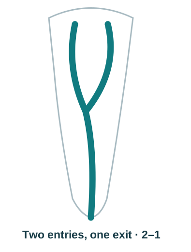 2 / 3 · Two distal pathways merging into one
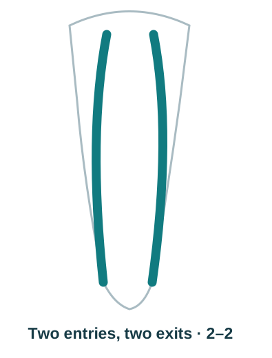 3 / 3 · Two separate distal pathways
03 / Chamber-floor landmarks
Locate the CEJ and the floor–wall junction.
Krasner and Rankow examined 500 extracted teeth and described relationships that make access more systematic. Apply these observations together and recognise when calcification, previous cutting or unusual anatomy has changed the map. [1]
CEJ and root axis
The cementoenamel junction is a more consistent reference than the outline of a heavily restored crown. Estimate chamber position and depth before cutting.
Colour and junction
The floor is generally darker than the chamber walls. Inspect its full junction with the walls, particularly the angles and the ends of developmental grooves.
Symmetry and its limits
Use buccolingual pairing around a mesiodistal reference as a search aid in ordinary lower molars. Expect variation in spacing and symmetry, especially in C-shaped systems.
Use the tooth’s landmarks to control cutting. Published inter-orifice distances vary with the tooth, population and measurement method. Preserve the floor’s landmarks and reassess whenever the expected anatomy is not present.
05 / Anatomical variations
Middle mesial canals, extra roots and C-shaped systems.
Inspect between MB and ML.
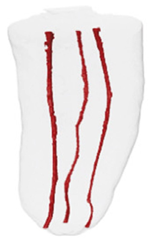
A middle mesial canal may arise within the mesial developmental groove. It can remain independent, merge with MB or ML, or be associated with a coronal fin. A dark line is not proof of a separate canal, and repeated deep troughing can sacrifice valuable dentine.
Versiani et al. found an overall frequency of 18.6% in extracted Brazilian and Turkish mandibular first molars, with different rates in the two groups (22.1% and 14.8%). Confluent anatomy predominated; only 3 of the 48 teeth with an MMC had the fully independent configuration. The mean minor diameter of independent MMC openings was 0.16 mm. These laboratory measurements do not establish clinical detection rates or NZ prevalence. They should not determine bur size. [3]

 1 / 4 · Search zone between MB and ML
Hover, focus or tap a canal system to see the source image.
An extra distal entry may belong to an extra root.
A separate distolingual root is termed radix entomolaris; a supernumerary buccal root is termed radix paramolaris. Look for an additional root outline, unexpected curvature or a canal that does not match the visible root’s position. Establish the root configuration before assuming that every distal opening lies in one broad root. [11]
Check lower second molars for a C-shaped system.
Fused roots, a ribbon-like or semicolon-shaped opening, or seemingly disconnected entries may belong to a C-shaped system. Its cross-section can change from continuous to interrupted or separate spaces along the root. A round coronal opening does not exclude that arrangement below. Min and colleagues’ micro-CT study of 44 selected C-shaped second molars showed why the usual floor patterns and symmetry rules may not apply. This selected sample cannot estimate C-shaped prevalence in all lower molars. [5]
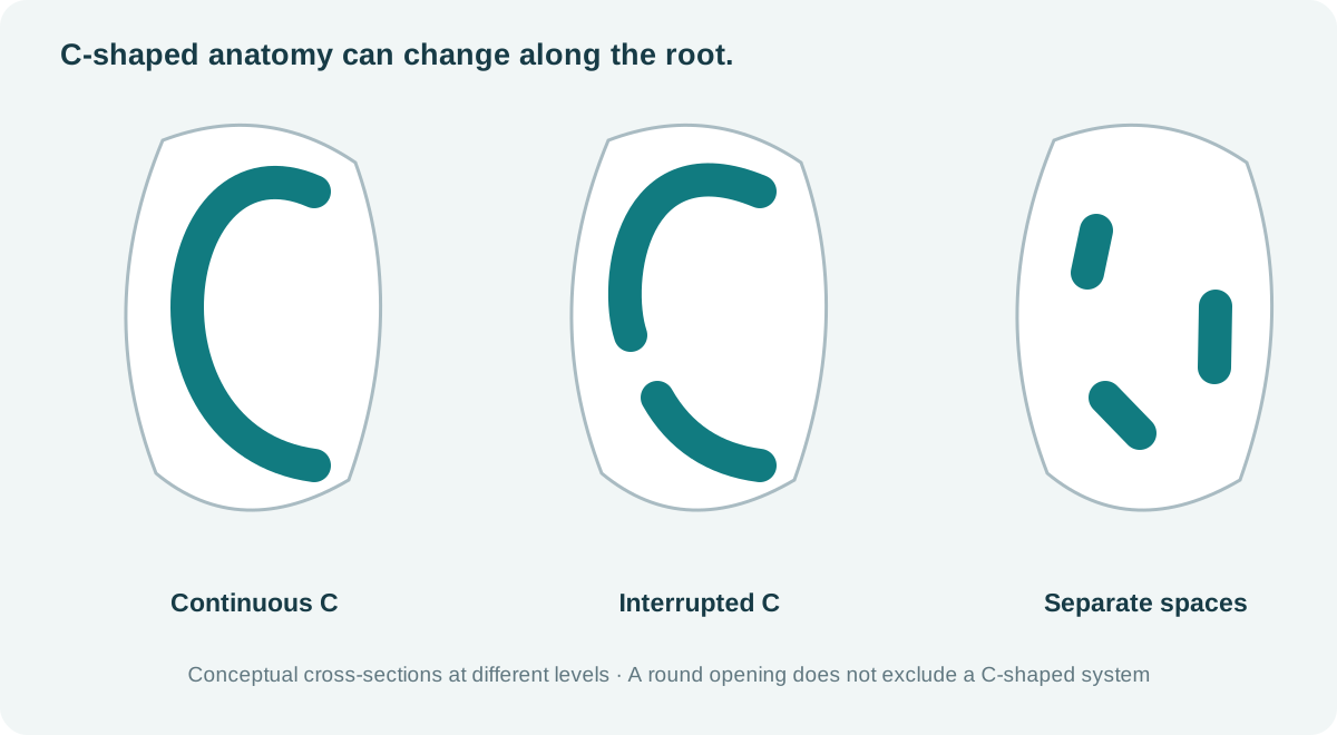
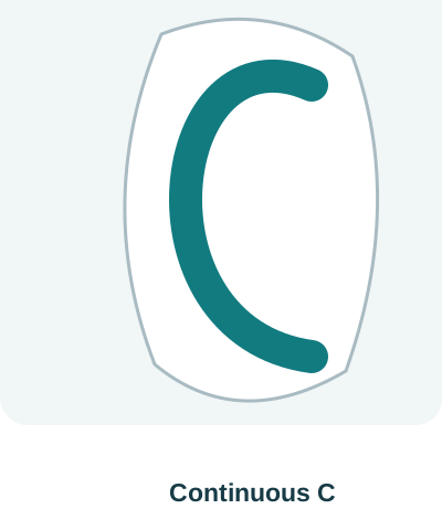 1 / 3 · Continuous C-shaped space
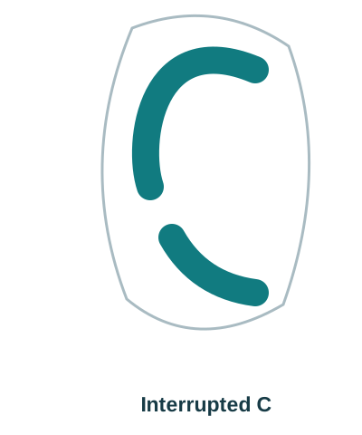 2 / 3 · Interrupted C-shaped space
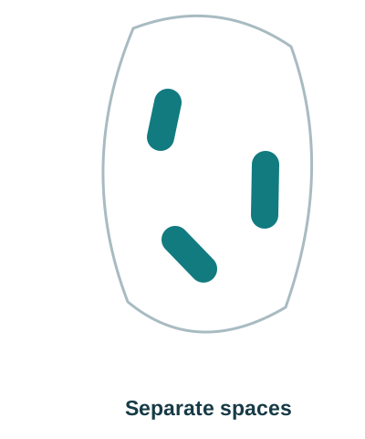 3 / 3 · Separate spaces in a C-shaped system
06 / Micro-CT images and videos
Marco Versiani’s Root Canal Anatomy Project
Professor Marco A. Versiani’s Root Canal Anatomy Project uses micro-CT reconstructions to make canal systems visible from multiple directions. Use the original images and videos to look beyond the access opening: follow canal divisions, confluences, isthmuses, lateral branches and the relationship between internal and external anatomy.
Micro-CT is an ex vivo research method; routine clinical CBCT does not reproduce its fine anatomical detail. EndoTech drew the diagrams on this page to explain the anatomy. Follow the links above to see the Project’s original micro-CT images.
07 / Chairside checks
From assessment to canal negotiation.
- Before access
Record symptoms, previous treatment and review interval; assess restorability, coronal seal, cracks, six-point probing and baseline periapical images.
- Orient the tooth
Identify mesial, distal, buccal and lingual from the tooth and images. Use the CEJ and root axis when a crown or restoration distorts the occlusal landmarks.
- Expose the chamber floor
Isolate with rubber dam; clear chamber contents and obstructing roof sufficiently to see the floor–wall junction. Do not flatten or gouge the floor.
- Audit the distal root
Inspect the full buccolingual extent of the distal opening. If it is eccentric, assess the opposite end and any connecting groove before accepting one canal.
- Audit the mesial root
Confirm MB and ML; inspect the groove between them for a middle mesial entry or fin. Treat a groove as anatomy to assess, not proof of a third canal.
- Confirm the pathways
Negotiate gently with small precurved hand files. Establish working length for each pathway; use angled views when files overlap and consider confluence.
- Disinfect the spaces
Maintain irrigant exchange, replenishment and safe backflow; use activation when appropriate. Mechanical enlargement cannot reach every recess.
- Stop and reassess
When landmarks disappear, dentine thickness is uncertain or negotiation is unsafe, stop cutting. Reassess imaging, consider indicated CBCT, or refer.
Use additional angled periapical views when superimposition obscures the canal pattern. Consider limited-field CBCT when the examination and conventional images leave a specific question unanswered and the result could change management. Select an appropriate field and exposure, and interpret the entire volume; CBCT is not a routine screening step or a reliable way to exclude every fine crack. [8]
Stop cutting when the anatomy is unclear. Reassess the images and chamber landmarks, or refer before removing more dentine.
Evidence & original sources
References
The Facebook reel supplies the case discussion. Anatomical studies support the search principles and their limits. Laboratory findings do not establish a patient’s canal configuration or the outcome of a treatment.
- Krasner P, Rankow HJ. Anatomy of the Pulp-Chamber Floor. J Endod. 2004;30:5–16. Chamber landmarks and orifice-location principles.
- Gorduysus O et al. Localization of root canal orifices in mandibular second molars in relation to occlusal dimension. Int Endod J. 2009;42:973–977. Fifty extracted second molars; opening position and variation.
- Versiani MA et al. Middle mesial canals in mandibular first molars: a micro-CT study in different populations. Arch Oral Biol. 2016;61:130–137. DOI: 10.1016/j.archoralbio.2015.10.020. Published online in 2015; journal issue 2016.
- Fan B et al. Three-dimensional morphologic analysis of isthmuses in the mesial roots of mandibular molars. J Endod. 2010;36:1866–1869. Four three-dimensional isthmus patterns in a selected extracted-tooth sample.
- Min Y et al. C-shaped Canal System in Mandibular Second Molars. Part III: The Morphology of the Pulp Chamber Floor. J Endod. 2006;32:1155–1159. Chamber-floor variations in 44 selected C-shaped molars.
- Versiani MA. The Root Canal Anatomy Project. Original micro-CT teaching images and videos; first- and second-molar links above.
- Patel S et al. Position statement on longitudinal cracks and fractures of teeth. Int Endod J. 2025;58:379–390. ESE consensus supporting a combined clinical and imaging assessment.
- AAE / AAOMR. Use of Cone-Beam Computed Tomography in Endodontics: 2025 Update. Current imaging position statement announcement and linked guidance.
- Hsu YY, Kim S. The resected root surface. The issue of canal isthmuses. Dent Clin North Am. 1997;41:529–540. Cross-sectional isthmus classification.
- Weller RN, Niemczyk SP, Kim S. Incidence and position of the canal isthmus. Part 1. Mesiobuccal root of the maxillary first molar. J Endod. 1995;21:380–383. Complete and partial connections; this study concerns upper molars, not lower-molar prevalence.
- Calberson FL et al. The radix entomolaris and paramolaris: clinical approach in endodontics. J Endod. 2007;33:58–63. Additional-root recognition and treatment implications.
- Demirbuga S et al. Use of cone-beam computed tomography to evaluate root and canal morphology of mandibular first and second molars in Turkish individuals. Med Oral Patol Oral Cir Bucal. 2013;18:e737–e744. DOI: 10.4317/medoral.18473. Table 1: CBCT canal counts.
Case source: Endo simplified’s original Facebook post. For dental professionals. Apply the findings to the individual tooth, diagnosis, imaging and operator’s training.